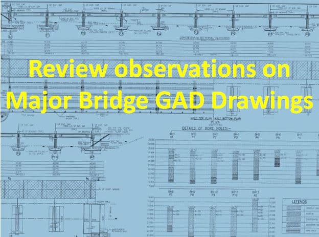
Review observations on Major Bridge GAD Drawings
Content Brief:
Review on Major Bridge GAD Drawings: This content pertains to the Review observations on major river bridge GAD drawings. These observations are made by the IE following the concessionaire’s submission of GAD drawings. The details and letters contain the following information:
-
Major bridge General arrangement drawings submission.
-
Review observations on drawings.
-
The observations, including the clarification and justification needed on the following
a. Geotechnical Report
b. Hydrological data ,
c. HFL for deciding the factors like Free Board and size of the piers.
d. Calculation for Energy Slope
e. Effective linear way
f. Detailed dimensions for foundation and sub structure
g. Precast diaphragms, Pre cast girders, bearings, span lengths, Slope protection measures. h. Further an updated, certified design addressing the points is requested for further review.
-
Additionally, there are elements that are not consistent with the Concession Agreement (CA).
-
Finally, provide IE feedback in line with the review.
-
The key terms concerning the review of drawings and documents are outlined in CA are highlighted in FAQ’s.

Preliminary review of GAD Drawings for Major River Bridge.
The following are the preliminary review observations on GAD drawings of major river bridge followed by the concessionaire submission for review and adopt for permanent construction works.
Case-1
| To
The Concessionaire
Subject: submission of design reports and construction drawings for major bridge at km.10+906-regarding
Dear Sir,
With reference to your submissions, reviews have been done as per Clause 12.3 of CA (construction of the project highway- drawings)and please find our Sr Bridge Design Engineer comments.
(A) General
- The Concessionaire should mention in the covering letter the specific clause of the CA under which submissions are made to IE. In the Concessionaire’s letter No. 481 dated 2-6-24 it is mentioned that this has been complied – but the letter no. 482 dated 2-6-24 does not comply to this requirement.
- The drawings have been marked as “GOOD FOR CONSTRUCTION”. The CA does not specify that GFC drawings are to be submitted to IE for review and the GFC mark is purely for convenience of Concessionaire. In future the Concessionaire should mark the drawings “FOR REVIEW”. Under no circumstance the review of IE is to be treated as endorsement of GFC status of drawing.
- The IE has reviewed the drawings as required under Clause 12.3 of CA. The Concessionaire should provide documentation to demonstrate they have complied to IRC SP 047 Guidelines on Quality systems on For Road Bridges Item 2.3 of Table 3.1 (QUALITY ASSURANCE REQUIREMENTS)
- As per CA a new parallel bridge (eccentric widening) is proposed at design chainage 10+895 of length 200 m and width 13.75 m. The Concessionaire has proposed concentric widening, length 140.305 m (5.425 +7 x 5.4 +3.48+9 x 10.4) and total width 29 m (13.75 +1.5 +13.75). Concessionaire to specify details for deviation from the CA and approval given by client for these deviations.
- Concessionaire should submit General Arrangement Drawing(s) to the Government as required under clause 12.3 (f) of CA under intimation to IE.
- Hydrological Investigation and Sub surface exploration reports are not available in the design note. How the founding levels have been fixed with reference to scour and SBC?
- Why earth pressure is considered for design of A1. Whether load from box structure is considered in design of abutment footing?
(B) Drawings
- Clear expansion gap is to be provided between the box structure and abutment A1 up to founding level of box structure. The back face of abutment stem may be provided without batter and box wall of uniform thickness.
- Slope of dry stone pitching is provided 1:1.5 uniformly-generally the slope varies from 1:1.5 to 1:2 (embankment slope). Dimension 9250 mm is to be accordingly corrected.
- Note 3 (G-01 sht. 1/3) is not clear.
- Note 19 (G-01 sht. 1/3): delete reference to development length.
- At many locations IS 2502 is wrongly written as IS 2520.
- Buried type expansion joints are not suitable for this structure. Existing expansion joints should be replaced.
- Table of grade and cover (G-01 sht 2/3) – Cover for super structure = 50 mm vs. 40 mm on sht 1/3.
- New kerb to be provided in the median – please review from safety consideration.
- Section Z-Z (E-01 sht. 3/4) – show height dimensions and crash barrier.
- Details of existing foundations should be ascertained by trial pits first and thereafter proposals to be prepared.
- Drawings/instructions to ensure safety of traffic during widening to be prepared.
- Regarding drawing no. MISC-03
- Existing cutwater shape to be shown as actual for every type.
- The designer MUST ascertain whether existing piers are RCC or PCC and modify drawing accordingly.
- Consider cut water arrangement as shown below for both RCC and PCC
- The existing pier is shown as RR masonry. It is RCC or PCC.
This is for your information and compliance.
Thanking you |
Case-2
|
To
The concessionaire
Subject: Preliminary review of GAD Drawings for Major River Bridge.
Ref: Your Letter No. XX, submission of GAD drawings
-
In connection with the preliminary review of the General Arrangement Drawing (GAD) for the Major River Bridge, we would like to intimate you of our following observations.
-
The total submission comprises of GAD, Geotechnical Report and Hydrological data bear no signature from the authorized persons. Which are absolutely unacceptable to us.
-
HFL plays an intrinsic role while deciding the factors like Free Board and size of the piers. Though an elaborative calculation is being submitted but it is not being supported by any Government Authentication what so ever.
-
Since, there are varieties of opinions related to the HFL of last significant flash flood. So we are not in a position to accept the proposed HFL without any supportive documents from the appropriate authority.
-
Your submission prepares many vital dimensions without supportive information like
a. Calculation for Energy Slope, do not being supported by any document.
b. Effective linear way is being shown as 523 mt without any supporting calculations.
c. Detailed dimensions for most of the substructure members are not being provided.
d. No detailed information’s for the foundations and substructure of the existing Bridge are being provided.
e. Footpaths are being shown in the wrong side
-
The reasons behind the maintaining of different top levels of the pile caps for the proposed and the existing bridges are not being clear.
-
The superstructure drawing lead us to think the longitudinal girder as trough typed closed girders, where as the corresponding note proposes the same as PSC-T girder with deck slab – which should be followed?
-
In the shaded elevation at support, it appears that the entire super structure consists of diaphragms only. The precast diaphragms are being connected with cast in situ diaphragms. Nothing has been mentioned about the concrete, in between the vertical cast in situ diaphragms and the face of the longitudinal troughs. Details are to be submitted.
-
-
In the side view of pier and pier foundations, the girders of the superstructure are being shown near the support. The normal practice is that such widening near the support are generally being provided for T girders only. Pleased elaborate your stands.
-
Reasons are not being clear for the proposal for Elastomeric Bearings, in spite of the span being 40mt, or more
-
There are no proposals for pitching with toe protection for the sloping embankment in the approach portion, which may spill through the piles to river, as the dirt wall is being proposed on the pile caps only.
-
The SBC of rock at foundation level must be shown in every pier and abutments.
Please comply the above points and resubmit the proposal with all the requisite credentials.
Thanking you.
|
Comments of the Senior Bridge Design Engineer of major bridge drawings
| To
The Concessionaire
Subject:- Comments of the Senior Bridge Design Engineer ch: 19+919- Reg
Dear Sir,
With reference to the review of Final drawings for the Bridges, in the Project Highway our Sr. Bridge Design Engineer has reviewed the following drawings and consecutively made his observations-
Drawings
Piers and abutments (dimensions) mismatches among drawings. Dimensions of stems should be clearly shown in drawing.
Bore hole data to be fumished in GAD.
Locations of drainage spouts to be marked in GAD
Slope of stone pitching on earthen slope should be shown and also corresponding dimensions of cantilever return to be checked.
Maximum scour level should be shown in GAD
Type of expansion joint to be shown in GAD
FRL shown in GAD at the outer edge of crash barrier. Please clarify
Note no. 9, 30 and 34 (Drg No. G-01-Shit 1) to be reviewed.
Wearing coat seems to be provided below the crash barriers drawing no. G-01 sheet no. 3 of 3 in “typical section of pier Please rectify
Design of superstructure:
Soft copy of staad file required to check the stresses considered in design calculations
Design of sub structure:
1. Design of pier P1, Page 29, Values of P, ML and MT not displayed
2. Unit weights of materials are not considered as per IRC 6-2010.
So, you are being instructed to comply his recommendations and submit the final drawings for our necessary certifications.
Thanking you,
|
A Note to the Visitor on Review observations on Major Bridge GAD Drawings
It is that a few important and mandatory aspects are only discussed herewith. Kindly note that the above inspection observations are considered examples. You may adopt the gist of the subject and change it to suit the current need. And before using this content in your letter drafting, you need to ensure the specific CA contractual conditions and other aspects, etc.
Also read the BI and BBD letters and the NSV Report Letter: Request for Programme, Submission, Review of Observations, and Comments.
You can find various sample draft formats for highway operation and maintenance correspondence.
FAQ’s related to Review observations on Major Bridge GAD Drawings
[rank_math_rich_snippet id=”s-371c3122-9944-4dea-8b12-0eb686baae70″]